rat7761
Member
- Joined
- Jul 28, 2008
- Messages
- 563
- Reaction score
- 2
This is for those of you who want to purchase Doug Thorley long tube headers but are wondering what's involved with the installation of a URD rear A/F sensor simulator. Be sure to disconnect your battery before starting.
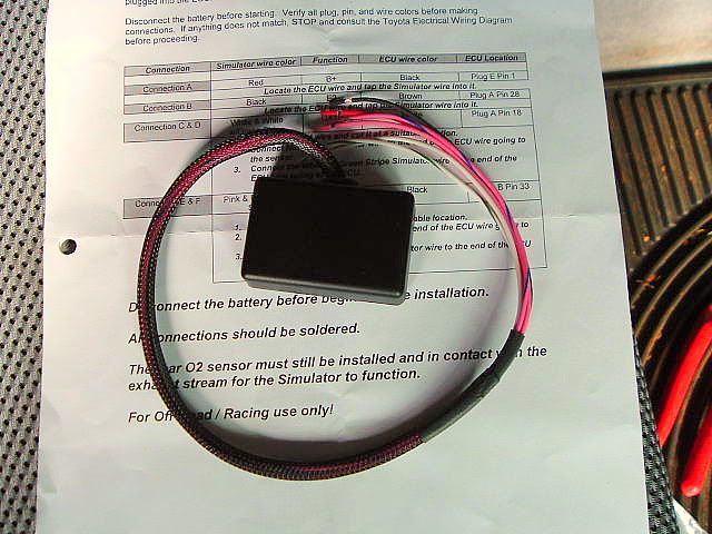
The simulator is small and there are 6 wires. Note: Soldering all connections is suggested but I did it the lazy way with butt connectors and wire taps.
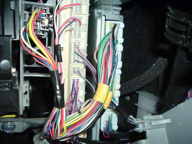
The ECU is located behind the glove compartment. No tools are required to remove the glove compartment. The ECU is the one furthest to the right.
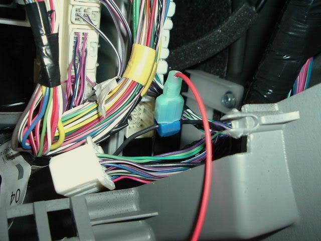
The 1st connection I made was tapping into the black ECU wire (plug E pin 1). This is a 12V source. The red wire from the simulator is connected.
The 2nd connection was to the brown ECU wire (plug A pin 28). This is a ground. The black wire from the simulator was tapped into the brown ECU wire.
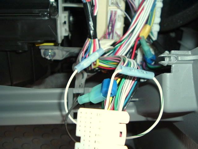
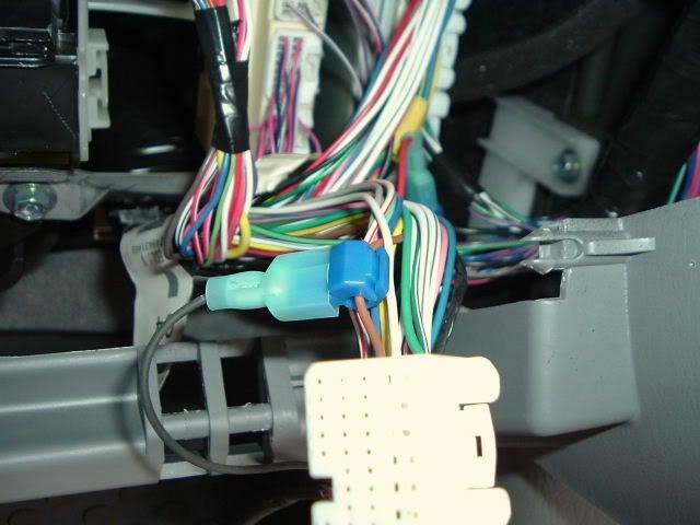
The next task was to locate the white ECU wire (plug A pin 18). This is the bank 1 sensor wire. This wire was cut and the white simulator wire was connected to the ECU wire going to the sensor. The white/green stripe wire from the simulator was connected to the ECU wire going to the ECU.
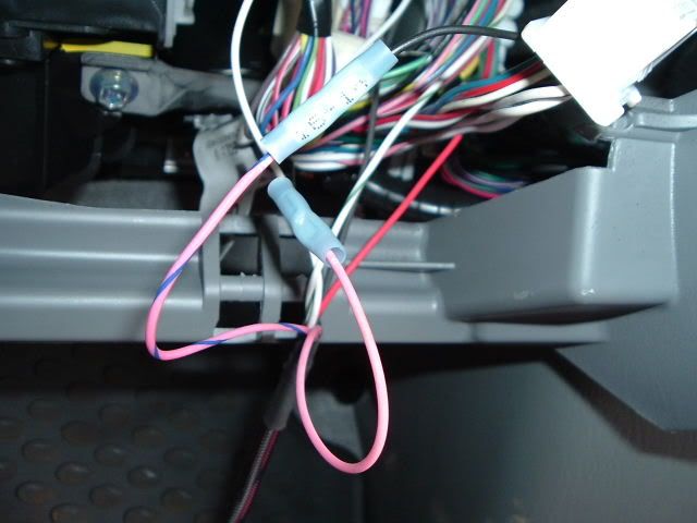
Finally, the black ECU wire (plug B pin 33) was located and cut. This is the bank 2 sensor wire. The pink simulator wire was connected to the ECU wire going to the sensor. The pink/blue stripe wire was connected to the ECU wire going to the ECU. Find a suitable location to zip tie the simulator out of the way and you're done. Note: It looks like the pink wire is connected to a white wire in the pic but it is connected to the black ECU wire going to the sensor which is hiding.
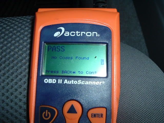
I took a test drive and no codes were present. :smile:
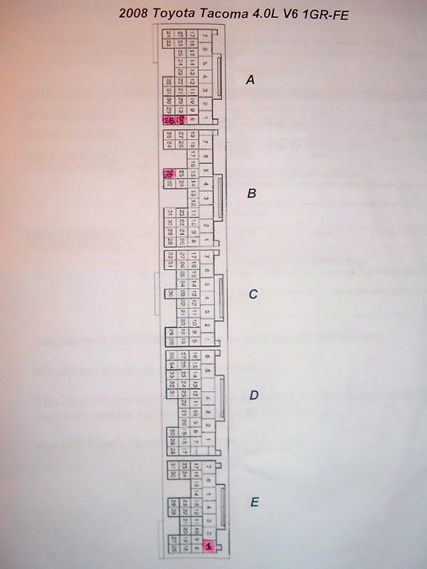
Pin locations. The locations are how you would see them if you were looking at the ECU from the passenger seat.
The simulator is small and there are 6 wires. Note: Soldering all connections is suggested but I did it the lazy way with butt connectors and wire taps.
The ECU is located behind the glove compartment. No tools are required to remove the glove compartment. The ECU is the one furthest to the right.
The 1st connection I made was tapping into the black ECU wire (plug E pin 1). This is a 12V source. The red wire from the simulator is connected.
The 2nd connection was to the brown ECU wire (plug A pin 28). This is a ground. The black wire from the simulator was tapped into the brown ECU wire.
The next task was to locate the white ECU wire (plug A pin 18). This is the bank 1 sensor wire. This wire was cut and the white simulator wire was connected to the ECU wire going to the sensor. The white/green stripe wire from the simulator was connected to the ECU wire going to the ECU.
Finally, the black ECU wire (plug B pin 33) was located and cut. This is the bank 2 sensor wire. The pink simulator wire was connected to the ECU wire going to the sensor. The pink/blue stripe wire was connected to the ECU wire going to the ECU. Find a suitable location to zip tie the simulator out of the way and you're done. Note: It looks like the pink wire is connected to a white wire in the pic but it is connected to the black ECU wire going to the sensor which is hiding.
I took a test drive and no codes were present. :smile:
Pin locations. The locations are how you would see them if you were looking at the ECU from the passenger seat.
Last edited: